|
||
|
Test Equipment Load Boards / Interface Boards
A
load board,
interface board,
or DUT board is a circuit board designed to serve as an
'interface'
circuit
between the automatic test equipment
(ATE)
and the device under test
(DUT).
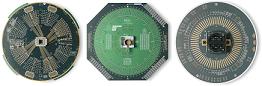
Fig. 1. Photos of ATE Interface Boards or Load Boards
An ideal load board introduces no distortion, noise, delays, nor errors to the testing process of the DUT. This means that an ideal load board is one that doesn't seem to exist at all, i.e., as if the DUT were directly connected to the ATE. To come out with a load board as close as possible to this ideal one is the challenge to every engineer who designs load boards.
Load boards are often customized to a specific device or group of devices. As such, complete, ready-to-use load boards are not normally available off-the-shelf. The usual way to acquire a load board for a new product is to have it designed and fabricated. Thus, most test engineering groups have a certain level of expertise in designing and fabricating a load board.
A load board consists of a PCB with a test socket or handler interface as well as a variety of components (IC's, resistors, capacitors, inductors, relays, connectors, etc.) that make up the load board's test circuits. The typical laminate for the load board PCB is the FR4 (Flame Retardant 4 fiber glass). The number of layers of a load board PCB also varies, depending on the complexity of the design. Some load boards for complex devices may even have more than 20 layers.
<Proceed to Page 2 - Designing Load Boards>
See also
Copyright © 2005. SemiconFarEast.com. All Rights Reserved. |
||